A design language is only as honest as the system that holds it up. This is the V1 structural thinking behind the collection — written as a set of questions, because that is what it still is.
Concept visualization — not a completed installation
01
Structure disappears
A concealed, interlocking skeleton carries every load. It is indexed, keyed and serviceable — and it is never part of the visible language.
02
Surface remains
The engineered optical carrier is the only thing the eye reads: continuous where geometry allows it, deliberately cellular where it does not.
03
Light becomes the artwork
Rear-projected light meets the surface from inside the form. The projector, its heat and its service access are architectural problems solved behind the skin.
04
Honesty is a material
Developable surfaces can be rolled. Doubly curved surfaces must be formed. Seams are designed or declared, never denied. Nothing is called seamless that is not.
01 / Fabrication routes
Four ways to carry a surface.
Which route a form takes is decided by its geometry, not by preference. A cylinder rolls. A saddle must be formed. A canopy may be cells by design.
A
Tensioned continuous skin
A compatible flat-coated carrier, rolled for shipping, captured at the perimeter and tensioned over planar or developable geometries (cylinders, cones, planes). Edge-bead capture, rear splices and tension adjusters never pierce the image area.
Suits
Veil Wall · Portal · Tower sleeve
B
Preformed monolithic optical shell
Form the compatible compound-curved carrier first; coat afterwards; inspect thickness, adhesion and scattering; mount via concealed peripheral structure. Nested, protected shipping — not presumed flat-pack.
Suits
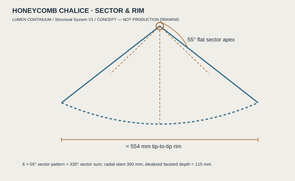
Chalice · Saddle · Helix sections · deeper petals
C
In-situ continuous coating
Assemble, level and stabilise the architectural substrate, then qualify field coating across prepared joints — movement, optical discontinuities, orientation and quality control all qualified, not assumed.
Suits
Premium architectural installations
D
Intentional optical cells
Structurally divided apertures with a designed visible rhythm. Beautiful boundaries are deliberate — and the overall surface is not physically seamless.
Suits
Petal Canopy · Spire facets · Chalice arrays
02 / Connector family
L-K1 to L-K6.
Six concealed connection ideas, each with its preliminary envelope and the questions that must be answered before any of it is drawn for fabrication.
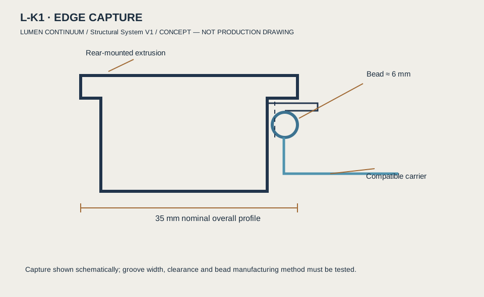
L-K1
Captured perimeter bead and rail
Preliminary
Preliminary 35 × 20 mm external aluminium rail envelope; ≈ 6 mm captured edge bead.
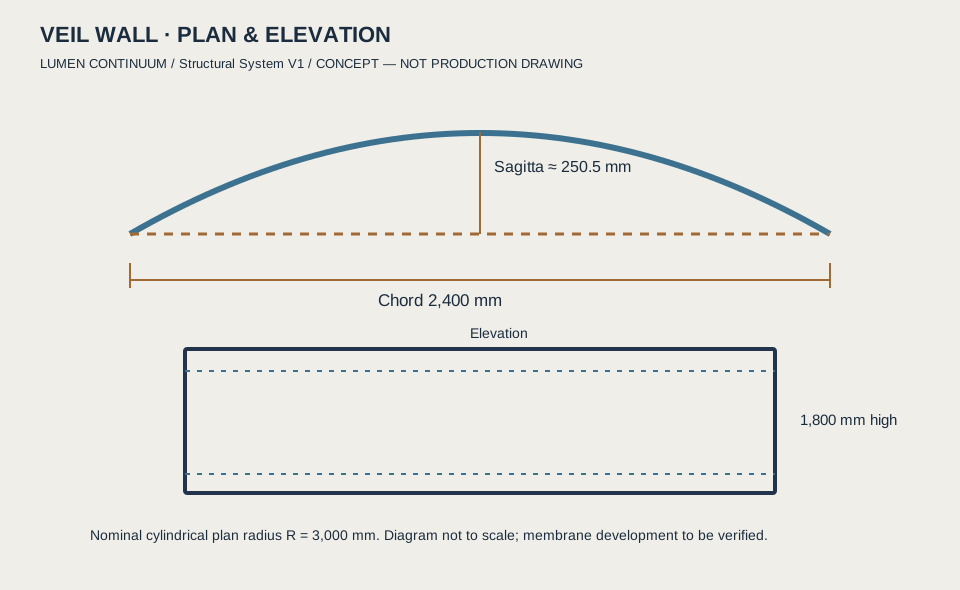
The proposed first large-format demonstrator. A plan — not a completed installation.
01
Roll a flat-coated carrier onto a cylindrical plan of R ≈ 3,000 mm; chord 2,400 mm, height 1,800 mm.
02
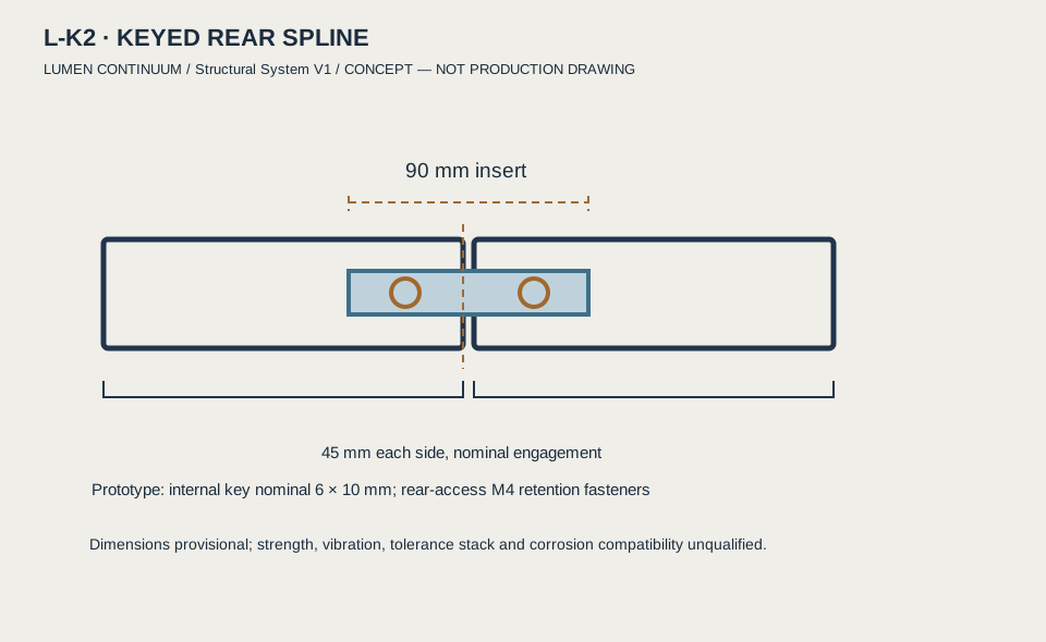
Curved top and bottom guides, two vertical edge rails, hidden keyed splices (L-K2), bead capture at the perimeter (L-K1).
03
Rear adjustable frame to hold the arc against twist; tension adjusters (L-K5) with positive travel stops.
04
Measure edge-to-edge brightness and sharpness under a controlled projector — publish what is measured, nothing else.
05 / Still required
What this page does not claim.
Every item below is engineering work that has not been done. Listing it is the point.
Structural load paths, tipping and anchorage for every freestanding form
Suspended-installation primary support and independent secondary restraint (Petal Canopy)
Electrical routing, projector containment, heat rejection and service access
Projector geometry and self-occlusion studies for 360° forms (Tower, Spire, Helix)
Coating behaviour on curved substrates: thickness, orientation, strain and scatter (Gate 0)
Fire, ingress and public-safety codes per jurisdiction
Preliminary design envelopes only. No verified photometric data, no load ratings, no code compliance and no production specification exist for any LUMEN form. If you are an engineer or fabricator who wants to argue with any of this, that is exactly the conversation we want.